

As machines become larger and more automated, What starts as a simple safety circuit can quickly turn into hundreds of wires, crowded control panels, and difficult troubleshooting . That’s one reason more manufacturers and OEMs are starting to explore networked safety systems like CIP Safety™.
CIP Safety™ enables allowing devices to work together seamlessly on the same network, reducing complexity and enhancing safety. But while CIP Safety™ continues to grow, traditional hardwired safety still plays an important role in many applications. The key is understanding when each approach makes the most sense.
Key Takeaways- Hardwired safety uses direct wiring between safety devices, safety relays, contactors, and safety plc inputs. - CIP Safety™ sends certified safety signals over ethernet ip using the common industrial protocol. - Hardwired safety makes sense for simple machines; CIP Safety™ scales better for distributed, multi-zone systems. - Modern industrial automation often blends both approaches for safe operation, diagnostics, and increased flexibility. - CIP Safety™ supports functional safety, rich diagnostic capabilities, and safety integrity level compliance up to SIL 3. |
Table of Contents (Jump to a Section):
How Machine Safety is Changing | Traditional Hardwired Safety | What is CIP Safety? | CIP Safety Architecture | Diagnostics and Troubleshooting | Hardwired vs. CIP Safety | Conclusion | Migrations from Hardwired to CIP Safety | Need Help with Machine Safety? | Resources | FAQ
How Machine Safety Is Changing
Machine safety devices have not changed much over the years in modern industrial environments. Emergency stops, light curtains, safety door switches, laser scanners, and safety mats still serve the same purpose: protecting people and equipment from hazardous motion and unsafe operating conditions.
What has changed since about 2010 is how these devices are connected, monitored, and integrated into modern automation systems.
As machines have become larger, faster, and more interconnected, traditional hardwired safety systems can become difficult to scale and maintain. Now, both safety and standard devices are integrated on the same network, replacing isolated systems. Large amounts of wiring, crowded control panels, limited diagnostics, and complex troubleshooting have pushed many OEMs and manufacturers toward more distributed safety architectures.
Defining Traditional Hardwired Safety
Hardwired safety is the traditional point-to-point approach we all know. Each device, such as an emergency stop, light curtains, safety sensors, safety interlock switches, or two-hand controls, is wired back to safety relays or safety PLC inputs in the main control panel.
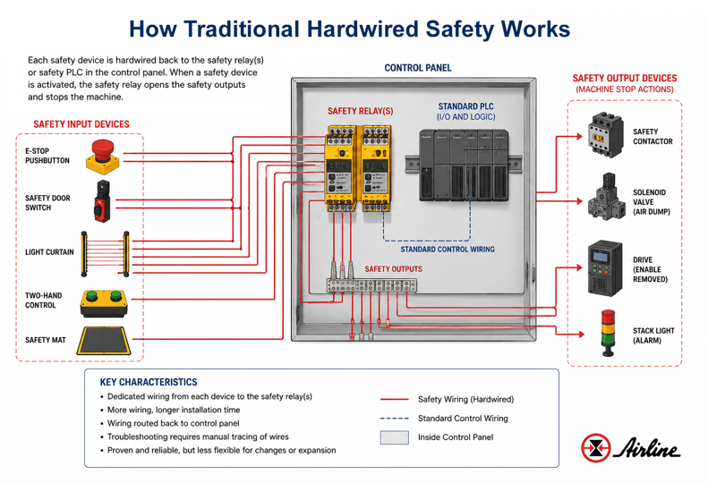
Most circuits are dual-channel and monitored. When an E-stop is pressed, both channels open, contactors de-energize, and hazardous power is removed. This does not depend on a network, communications, or application layer standards, which is why it has been trusted for decades in packaging, metalworking, and material handling.
Example: Consider a small press with three E-stops, one guard door, and one light curtain. Each device has conductors home-run to the cabinet. The safety system logic may be relay contacts or basic safety controller blocks.
With hardwired safety, troubleshooting is usually manual: Walk the machine, check LEDs, read drawings, and test continuity. But for fixed machines with low device counts, this is still a solid, low-risk system.
Advantages and Limitations of Hardwired Safety
 Hardwired systems are easy to understand, need no IP addressing, expose little cybersecurity surface, and are familiar to inspectors. They are often the lowest-cost option for simple machines.
The downside appears as systems grow. A line with 8 E-stops, 6 doors, and 4 light curtains may need dozens of multicore cables and hundreds of terminals. Adding devices can mean conduit, new cable, and panel redesign. Diagnostics are limited compared with status information and diagnostic information available from networked devices.
What Is CIP Safety™?
 CIP Safety™ is an extension of CIP, or Common Industrial Protocol, that allows CIP Safety™ data and safety data to travel over standard EtherNet/IP networks. CIP Safety™ operates alongside other application layer standards, enabling seamless integration within industrial automation environments. It was published by ODVA (standards development organization) in 2005 and is described as high integrity safety services for functional safety applications over standard industrial network infrastructure.
CIP Safety™ complies with international functional safety standards including IEC 61508 and ISO 13849 and supports SIL 3 safety applications. CIP Safety™ is designed to provide fail safe communication and high integrity between safety devices and standard devices, ensuring reliable and fault-tolerant operation in industrial settings.
CIP Safety™ has been certified by TÜV Rheinland for use in functional safety applications, ensuring its reliability in safety-critical environments. The protocol ensures fail safe communication, maintaining safety even in the event of faults. CIP Safety™ supports Safety Integrity Level (SIL) compliance up to SIL 3, as defined by IEC 61508, ensuring high safety standards in industrial automation. It also complies with IEC 61508 and ISO 13849, which provide methods for applying, designing, deploying, and maintaining automatic protection systems.
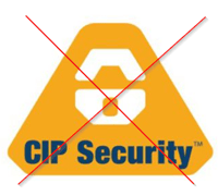
One thing to clarify: CIP Safety™ is NOT the same thing as CIP Security™; CIP Security addresses authentication and cyber protection. CIP Safety™ focuses on data integrity, transmission integrity, and ensuring safety.
How CIP Safety™ Works Over EtherNet/IP
CIP Safety™ allows both standard control data and safety data to operate over the same EtherNet/IP network.
The protocol uses what is known as a “black channel” approach. This means the safety integrity is handled by the CIP Safety™ protocol itself rather than depending on the physical network media. Because of this, safety communication can operate across standard industrial Ethernet infrastructure while still maintaining functional safety requirements.
Within the system, a safety controller — often called the safety originator — exchanges safety data with safety devices such as:
- Distributed safety I/O
- Drives
- Valve manifolds
- Remote safety modules
These devices act as safety consumers within the network.
To make sure communication remains reliable and safe, CIP Safety™ continuously validates the data being transmitted. The protocol uses mechanisms such as:
- Cyclic redundancy checks (CRCs)
- Timestamp monitoring
- Sequence counters
- Device identification verification
- Watchdog timing
These checks help detect:
- Communication faults
- Duplicated messages
- Delayed data
- Misrouted packets
- Device failures
If a fault or communication issue is detected, the system automatically places the machine into a safe state.
One of the major advantages of CIP Safety™ is that both standard automation devices and safety devices can coexist on the same EtherNet/IP network. This helps simplify machine architecture while allowing for more flexible and distributed machine designs.
In a modern CIP Safety™ architecture, components such as PLCs, safety controllers, distributed safety I/O, and pneumatic systems can all communicate together across the same network infrastructure while still maintaining certified functional safety performance.
CIP Safety™ can also operate across multiple industrial network topologies including star, ring, and bus architectures, helping support scalable machine designs.
Example of a CIP Safety™ Architecture
The diagram below shows an example of how multiple technologies can work together within a CIP Safety architecture.

In this example:
A Phoenix Contact PLCnext controller handles standard machine control (in panel)
An Omron NX Safety Controller manages the machine’s safety logic (in panel)
Banner RSI/O safety I/O modules collect signals from field safety devices (on machine)
An SMC EX600 system integrates pneumatic valve control into the safety network (on machine)
All of these components communicate over the same EtherNet/IP network using CIP Safety™.
Standard Machine Control
Every automated machine needs a primary controller to manage standard machine operations. This includes tasks like sequencing, communication, motion coordination, process control, and standard I/O handling.
 In a CIP Safety™ architecture, standard machine control and safety communication remain functionally separate while operating within the same system.
In the example shown in the diagram, a Phoenix Contact PLCnext acts as the primary machine PLC. It handles standard machine control functions and communicates with the safety system and distributed devices across the network.
Good Read: Top 4 Questions Answered About PLCNext
Safety Control
In addition to standard machine control, a CIP Safety™ system may require a dedicated safety controller that evaluates safety conditions and determines whether the machine can safely operate.
In this example, an Omron NX Safety Controller manages the machine’s safety logic and coordinates the safety response across the network.
Distributed Safety I/O
Instead of routing every safety device directly back to the main control panel, safety I/O modules can be mounted closer to the machine or work cell. These modules collect safety signals locally and transmit certified safety data across the EtherNet/IP network.
The distributed I/O architecture helps:
- Reduce wire runs
- Simplify installation
- Improve diagnostics & troubleshooting
- Make future expansion easier
In the diagram example, Banner RSI/O safety I/O modules are used to connect field safety devices into the CIP network, such as:
- E-stops
- Light curtains
- Safety switches
- Safety mats, etc.
Good Read: Stop Wiring Safety Like it’s 2005— Introducing RSio Remote Safe I/O
Pneumatic Safety Integration
Many automated machines rely on pneumatic systems for motion and actuation. In traditional hardwired safety systems, pneumatic safety functions often require separate wiring and dedicated safety circuits.
With CIP Safety™, pneumatic devices can become integrated directly into the machine’s safety architecture through network communication.
This allows pneumatic systems to:
- Safely remove air during a fault
- Place valves into a safe state
- Support coordinated machine shutdown functions
In this example, the SMC EX600 system provides pneumatic valve control and EtherNet/IP communication as part of the overall CIP Safety™ architecture.
Diagnostics and Troubleshooting: From Guesswork to Data

Traditional hardwired safety systems may only indicate a tripped relay or general fault condition. CIP Safety™ systems can provide detailed diagnostics through the HMI or control software, helping maintenance teams identify communication issues, device faults, and unsafe conditions more quickly.
This allows maintenance teams to identify the following more quickly and accurately:
- Communication faults
- Device failures
- Unsafe conditions
- Disconnected devices
Improved diagnostics can help reduce troubleshooting time, simplify maintenance, and improve overall machine uptime.
Hardwired Safety vs. CIP Safety™ Comparison
|
Feature |
Hardwired Safety |
CIP Safety™ |
|
Communication Method |
Physical wiring |
EtherNet/IP network |
|
Wiring Requirements |
High |
Lower |
|
Scalability |
More difficult |
Easier |
|
Troubleshooting |
Manual tracing |
Advanced diagnostics |
|
Installation Time |
Longer |
Shorter |
|
Panel Space |
Larger |
Smaller |
|
Flexibility |
Limited |
High |
|
Device Expansion |
More wiring required |
Easier to add devices |
|
Network Dependency |
None |
Requires network infrastructure |
When Hardwired Safety Still Makes Sense:
For compact machines, one or two E-stops, one guard door, limited expansion, harsh locations where Ethernet is impractical, or budgets that do not justify networked safety.
When CIP Safety™ Is the Better Choice:
Large lines, modular machines, robot cells, multi-zone systems, and plants that need diagnostic information for higher OEE. It also helps OEMs configure machine variants without rewiring each design.
Conclusion
Hardwired safety remains practical for simple machines. CIP Safety™ is the stronger fit when wiring, diagnostics, modularity, and expansion become important. If you are designing a new machine or upgrading a line, evaluate the safety functions first, then choose the architecture that provides the safest and most maintainable result.
Planning a Migration from Hardwired Safety to CIP Safety™
Most manufacturers do not replace an entire safety system all at once. A gradual approach is usually easier and lower risk.
Many companies start by using CIP Safety™ on:
- New machine builds
- Robotic cells
- Machine additions
- Upgraded production areas
Existing safety devices can often remain in place by connecting them through distributed safety I/O modules instead of rewiring the entire machine.
During the migration process, it is important to:
- Validate required SIL and PL safety levels
- Document network layouts and device connections
- Verify safety communication between devices
- Test all safety functions before production startup
Proper planning helps ensure the system remains safe, reliable, and easier to maintain as the machine architecture evolves.
Need Help With Machine Safety or Distributed I/O?
Airline supports manufacturers, OEMs, and integrators with:
- machine safety solutions
- distributed I/O systems
- pneumatic safety integration
- industrial networking
- automation support
Whether you’re designing a new machine or upgrading an existing system, our team can help you evaluate the right safety architecture for your application.

Additional Resources
Stop Wiring Safety Like it’s 2005— Introducing RSio Remote Safe I/O
Top 4 Questions Answered About PLCNext
On-Demand Machine Safety Webinar
FAQ:These answers address practical questions engineers and maintenance teams often ask. |
Can I mix hardwired safety and CIP Safety™ on the same machine?Yes. Hybrid systems are common. A local E-stop loop can feed safety relays while distributed devices communicate through CIP Safety™, as long as the total safety design documents the required SIL or PL.
Do I still need safety relays if I use CIP Safety™?
Sometimes. Many systems use safety PLCs and safety I/O instead of relay banks, but safety relays, contactors, and disconnect devices may still remove hazardous energy.
How Does CIP Safety™ Help Ensure Reliable Communication?CIP Safety™ uses built-in checks such as CRCs, sequence counters, and timestamp monitoring to detect communication errors, corrupted data, delayed messages, and device faults. If a problem is detected, the system automatically places the machine into a safe state.
What kind of network infrastructure do I need for CIP Safety™?
Use industrial EtherNet/IP infrastructure, managed switches, good cabling, and documented topology. Bandwidth is usually modest, but latency, determinism, and segmentation matter.
How does CIP Safety™ affect system commissioning time?
For large systems, CIP Safety™ can save time during design, programming, and troubleshooting by reducing wiring checks. The work shifts to network configuration, device discovery, validation, and confirming that safety consumers receive the right safety data.
Is CIP Safety™ suitable for wireless safety applications?
Yes, in properly validated wireless systems. Designers must account for latency, packet loss, watchdog timing, and safe reaction time before production use.
Does CIP Safety™ Mean the Same Thing as Clean-in-Place (CIP)?No. In industrial automation, CIP Safety™ refers to Common Industrial Protocol Safety, a network-based machine safety communication protocol used over EtherNet/IP networks. In food, beverage, and pharmaceutical industries, CIP can also stand for Clean-in-Place, which refers to automated equipment cleaning systems. The two technologies are unrelated aside from sharing the same acronym. |
Leave Comment