Editor's note: This blog has been updated April 2024 for comprehensiveness
Circuit breakers are essential devices in electrical systems, protecting against harmful overcurrent conditions. An improperly-selected circuit breaker causes, at best, nuisance tripping. At worst, it causes damage to electrical equipment, electrical fires, and serious or fatal injuries. A critical factor in selecting circuit breakers is understanding the trip curve, which visually represents how quickly it will trip or open in response to different levels of overcurrent. But trip curves are notoriously confusing, so keep reading to learn the basics of trip curves to select the most appropriate and cost-effective breaker for your application.
Skip to a Section
What are Trip Curves? | Trip Curve Types | UL 1077 or UL 489? | How to Choose
What are Trip Curves?
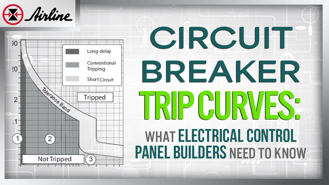
Circuit breaker trip curves are graphical representations of the response time of a circuit breaker to overcurrent conditions. They show the relationship between the level of current flowing through a circuit and the time it takes for the circuit breaker to trip or interrupt the current. An example of a trip curve is shown below.

The trip curve helps electrical control panel builders understand how a circuit breaker will behave under different fault conditions, such as overloads or short circuits. By matching the trip curve with the characteristics of the application, electrical control panel builders can select the correct size and type of circuit breaker, with minimal or no nuisance tripping, at the lowest possible cost.
Trip Curve Types
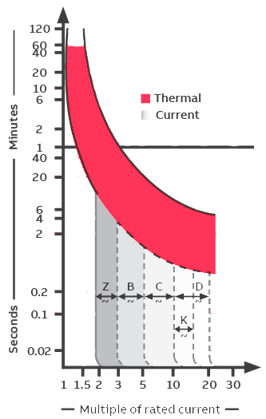
 A circuit breaker trip curve typically consists of three regions: the thermal region, magnetic region, and instantaneous region. The graph to the left compares the trip curves defined by IEC standards.
Thermal Region of Trip Curve
The thermal section of the trip curve responds to overloads (sustained or long-lasting overcurrent conditions) and is represented by the top/red area of the left graph. Therefore, a circuit breaker with a thermal trip curve is better suited for high-inrush current applications. The thermal trip curve is typically curved, reflecting the fact that the response time of the circuit breaker increases as the level of overcurrent increases. The thermal trip unit responds relatively slowly yet consistently.
Magnetic Region of Trip Curve
The magnetic current section of the trip curve responds to short circuits and is represented by the bottom/gray area of the graph above. It relies on a magnetic coil or solenoid opening when the overcurrent’s design limit is reached. The magnetic trip curve is typically a straight line, reflecting the fact that the response time of the circuit breaker is nearly instantaneous for high levels of current.
Characteristics of the magnetic/short-circuit trip unit
The characteristics of the magnetic/short-circuit trip unit and applications of each curve, from most to least sensitive, are:
Z: Trips at 2 to 3 times rated current. This is suitable for highly sensitive applications, e.g., semiconductor devices.
B: Trips at 3 to 5 times rated current.
C: Trips at 5 to 10 times rated current, making it suitable for medium inrush currents.
K: Trips at 10 to 14 times rated current. This suits loads with high inrush currents, mostly for motors and transformers.
D: Trips at 10 to 20 times rated current, making it suitable for high starting currents.
Instantaneous Region of Trip Curve
Sometimes, a trip curve will include an instantaneous region. The instantaneous trip curve is usually represented by a vertical line, indicating the maximum current level that the circuit breaker can interrupt without any delay.
What Do UL 1077 and UL 489 Mean?
In addition to trip curves, understanding UL certifications is another key component to selecting circuit breakers. UL-certified circuit breakers are a type of circuit breaker that is certified by Underwriters Laboratories (UL) and meets their requirements for construction, performance, and testing.
UL 489 and UL 1077 circuit breakers have different trip curves for specific applications. It is important to note that both standards require passing calibration, overload, endurance, and short-circuit tests, but UL 489 testing is more rigorous than UL 1077 testing. Choosing the appropriate UL-certified circuit breaker with the correct trip curve is vital to ensure proper protection and avoid damage and downtime.
What is UL 489?
UL 489 is a standard for molded-case circuit breakers, which are commonly used in commercial and industrial applications. One of the key features of UL 489 circuit breakers is their ability to interrupt short-circuit currents. This is important because short circuits can generate extremely high currents that can damage equipment and pose a safety hazard. UL 489 circuit breakers are also designed to be reliable and durable, with a long lifespan and minimal maintenance requirements.
What is UL 1077?
UL 1077 is a standard for supplementary protectors, which are commonly used in low-voltage DC or AC circuits. UL 1077 circuit breakers are designed to be compact and cost-effective, making them well-suited for applications where space and budget constraints are a concern. But it is essential to note UL 1077 devices are not considered circuit breakers by UL and are defined as supplementary protectors.
How to Choose a Circuit Breaker with the Right Trip Curve
 Selecting the right trip curve for a given application requires careful consideration of the characteristics of the load and the circuit. Experienced electrical control panel builders may be able to identify the appropriate trip curve for various applications, but for many electrical control panel builders, consulting with the device distributor can be helpful.
Here are four general guidelines to help select the appropriate breaker:
- 1. Identify the load type:
- The load connected to the circuit breaker is an essential factor to consider when selecting the trip curve. For example, loads like motors and transformers have high inrush currents, and a faster-acting trip curve can cause nuisance tripping. Therefore, a circuit breaker with a slower trip curve or a higher magnetic trip point is more suitable for these types of loads.
- 2. Evaluate the expected fault conditions:
- Fault conditions like overloads, short circuits, and ground faults have different characteristics and require other response times from the circuit breaker. Therefore, a circuit breaker with a trip curve that matches the expected fault conditions will provide optimal protection.
- 3. Consider system coordination:
- In a system with multiple circuit breakers, it is essential to ensure they coordinate correctly. For example, electrical control panel builders should select the trip curves to provide the downstream circuit breaker trips before the upstream breaker. This prevents unnecessary trips and ensures the fault is isolated to the smallest possible section of the system.
- 4. Consult with the manufacturer or supplier:
- The manufacturer or supplier of the circuit breaker can provide valuable guidance on selecting the appropriate trip curve for a given application. They can also provide information on specific trip curves compatible with the circuit breaker and recommend a suitable trip curve based on the application's requirements.
In general, understanding trip curves and UL certifications is crucial for selecting the proper protective devices for your electrical applications. If in doubt, a consultation with the manufacturer or value-add distributor, like Airline, can help make an informed decision.
- Have a question? Let us know!
Resources


Leave Comment