


-
Have you ever thought a situation was relatively safe until it really wasn't? Like in the movie Monty Python and the Holy Grail, King Arthur underestimated the harmless white bunny until it turned out to be a killer rabbit!
-
You should also never underestimate the power of your hydraulic equipment, even when seemingly motionless and safe. It may be tempting to reach in and perform routine maintenance when the system isn't moving. But, residual fluid can suddenly expose workers to unexpected and uncontrolled release of hazardous energy with serious health consequences.
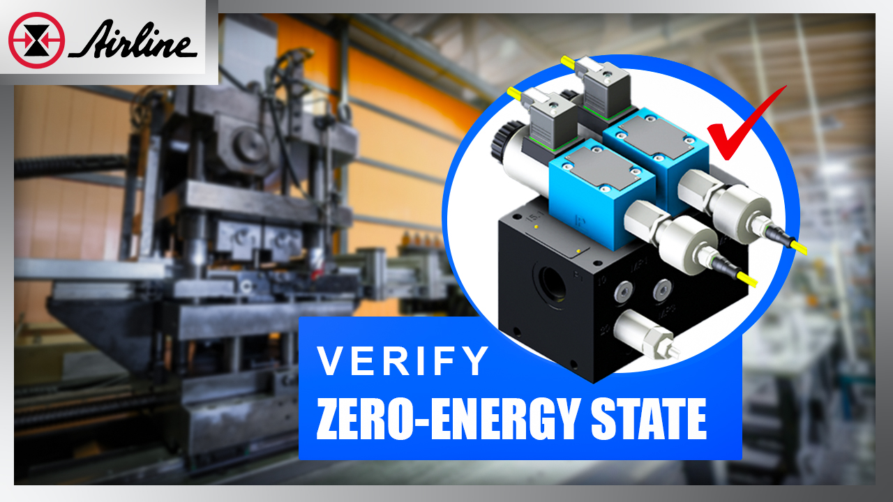
That's why I'm excited to share a hydraulic valve assembly that lets you know for certain if there's zero chance your hydraulic machine can activate and that it's truly safe for maintenance. It's machine safety month here at Airline, and hydraulic safety should never be overlooked, so keep reading to learn more about this life-saving solution.
Skip to a section:
Problem | Solution | Safety Standards | Ease of use | Summary & resources
The problem: Safely accessing areas inside a hydraulic system
Operators and maintenance occasionally need access to an unsafe area of the machine, whether to clean a tool or remove a mangled part. But even when the machine is motionless, a single hydraulic system can store multiple “pockets” or “zones” of stored energy. When this energy is offered to the actuator, the system can produce uncontrolled motion to the system’s mechanisms, which is the last thing you want while a person is reaching inside. Moreover, especially for pressing machines like the one you see here, the machine’s sudden activation can lead to life-threatening injuries.
For this reason, it can be challenging for machine operators to know whether the machine is in a safe state for maintenance. Without a solution in place, they can make dangerous assumptions about the machine’s safety, like:
"If a hydraulic pump is shut off, there's no pressure in the system, so it's safe." (NOT TRUE!)
"If you activate a manual directional control valve when the hydraulic pump
is shut off, the system will bleed off, making it safe for maintenance." (NOT TRUE!)
"A hydraulic system can be safely de-energized by loosening a
connector to allow stored energy to vent off." (NOT TRUE!)
"When a hydraulic system has an accumulator, it automatically de-energizes the system when the pump is shut off, therefore making it safe to reach in." (NOT TRUE!)
So how can machine users know there's no chance that hazardous energy is stored in the machine, making it safe to perform maintenance? This dilemma is infamous, so we kept re-engineering this solution to help customers for over 10+ years and then made it a standardized assembly that Airline quickly offers.
The solution: Airline's monitored block & vent assembly
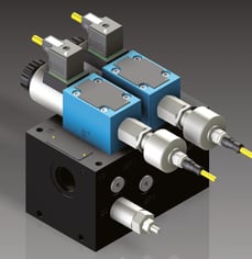
Airline's monitored block and vent assembly guarantees machine operators that their hydraulic machine is in a zero-energy, safe state for maintenance. And for its small size (6.5" x 6.5"), it certainly packs a punch. The assembly works by blocking the supply of hydraulic fluid to downstream machinery and venting any trapped pressure back to the tank, leaving machinery in a zero-energy state, allowing for safe access.
The diagram below shows how the valve assembly functions. The arrow entering at the bottom of the drawing illustrates the hydraulic fluid entering the assembly and being blocked by the first valve, having nowhere to go. If that valve is energized, the arrow shifts to the right, The arrow pointing down from the valve illustrates the pressure being vented out to the tank port (labeled T). If more fluid pressure remains, it moves to the next valve and is blocked and bleed there. The switches on the side of the valves indicate what position the valves are in, either safe (energized) or unsafe (not energized).
An optional pressure transducer is available to communicate further if the machine is in a safe state by reading zero pressure.
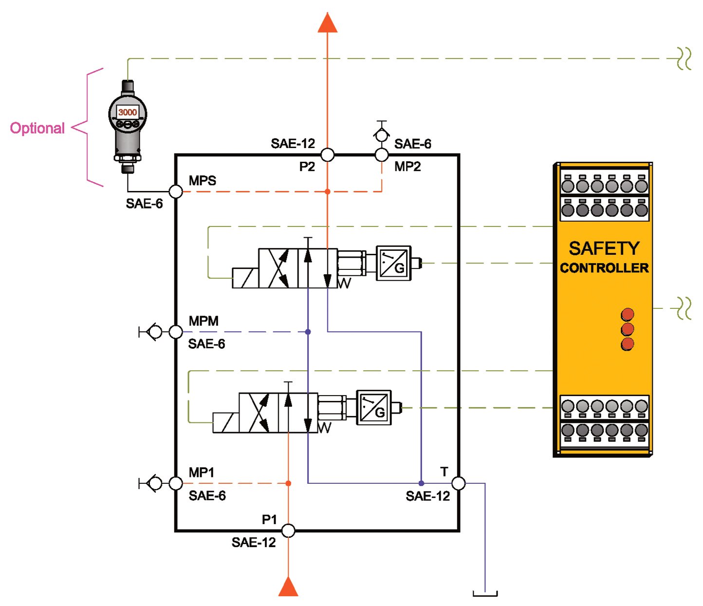
The valve assembly has two switching devices AND two monitoring devices that communicate with the safety controller. When the controller is notified the valves are in a safe position, it can allow safe entry into the system by unlocking a gate. So if all safety conditions aren't met, there is no way anyone is accessing the machine. Now that's working safe and smart!

What kind of valves are used in the assembly?
 Airline's monitored block & vent assembly utilizes two high-performance industrial valves from Bosch Rexroth, available in monitored and non-monitored configurations.
Applicable safety standards
Depending on the safety standards pertinent to your system (such as ANSI, ISO, and OSHA), you may be required to have one valve to block and bleed fluid from the actuator or two for redundant valving (like Category 4). This would mean you have two devices in series to keep the mechanisms from moving. Our engineered valve assembly already comes with two valves for optimal safety design and is compliant with the following standards:
• ANSI B11.2: Hydraulic and Pneumatic Power Presses - Safety Requirements for Construction, Care and Use
• ISO 13849: Safety of Machinery and Safety-Related Parts of Control Systems
• IEC 62061: Safety of Machinery: Functional Safety of Electrical, Electronic, and Programmable Electronic Control Systems
How easy is it to use?
Our block and bleed valve assembly can be installed onto virtually any industrial hydraulic machine, old or new. Once installed, it's incredibly user-friendly. With the optional pressure transducer, an operator needs to verify zero pressure and verify the machine's safety by looking. Without the pressure transducer, the switches located on the valves also indicate the valves' safe state. In addition, suppose the valve assembly is connected to the machine's controls. In that case, it couldn't be easier, as access to the device will only be granted when it's in a zero-energy state.
 Integrating the assembly into the safety controls is often the trickiest part of the installation, so many customers call on Airline to properly install the valve assembly. Airline's machine safety division, MPSA, has a dedicated team of safety control engineers who specialize in installing and verifying safety control systems of all kinds. Contact MPSA's team, who are happy to assist with installing this and other safety control systems.
For more information on the block and bleed assembly, download our spec sheet.
For a quote, contact us!
Monitored Block & Vent Assembly, Part # AHC1681081

Summary
Never underestimate the power of your hydraulics, especially when reaching in and doing some quick maintenance. The guesswork is removed by utilizing our block and bleed assembly, and you can know when your machine is in a zero-energy state.
Related Articles & Resources
Explore more hydraulic Technically Speaking articles
Explore more product spotlight Technically Speaking articles
Explore MPSA's Machine Safety Website
Leave Comment