


So, you have a new gas booster (or are about to buy one and doing some research). Adding a pressure control circuit will ensure your booster has enough inlet pressure to do the job, and will shut off reliably at a pressure of your choosing. Keep reading this technical guide and we'll walk through how to give your gas booster the controls it needs for a long, high-performing life. Let’s get started by taking a closer look at the selection and plumbing of these control components, and see how they apply to your system.
 A Technical Guide for Control Selection & Plumbing:

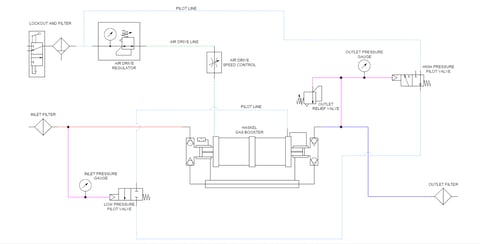
The air prep section starts with a lockout and a pneumatic filter. The maximum inlet pressure into this section is 150psi. The air drive regulator is used to reduce the driving pressure to the booster, and the filter needs to provide ISO Class 5 cleanliness or better. Depending on your application, your booster may be able to meet the desired flow rate and outlet pressure using a fraction of your line pressure. By doing so, you will ultimately save money on compressed air. The pilot line comes off the filter, or between the filter and air drive regulator. This control signal needs to be greater than 40psi and greater than or equal to the air drive pressure. The air drive speed control is a needle valve that is used to control the cycle rate of your booster. With most standard 5.75” drive boosters, the maximum allowed is 60 cycles per minute.
The gas section needs to be plumbed with lines appropriate to your desired pressures and flow rate. The pilot switches, gauges, and accessory components are typically plumbed with ¼” lines of appropriate pressure rating to make the unit's assembly easier. The inlet and outlet filters protect the gas booster from any incoming contamination as well as protecting the downstream equipment from any particulate generated by seal wear.
The meat of the booster control system lies in the proper selection of the pilot valves and relief valves. These components work with the external pilot port on the booster to provide on-off control of the booster system based on inlet and outlet pressure. This is all done pneumatically, so the controls are intrinsically safe. A pneumatic drive source is still the only utility required by the booster system.
Haskel offers three styles of pilot switches, but a "Style C" pilot switch is typically selected for the low-pressure pilot switch. These are the most difficult style to adjust, but help prevent tampering with the booster cutoff set-point. If there is a fixed pressure gas supply to the system, the switch will be selected and set for a value slightly under this supply pressure. If there is a pressure drop or if that line is shut off, the booster system will automatically stop. When drawing from a pressurized supply bottle, these switches are even more important. As the supply pressure drops, you will reach a point where the supply pressure is too low to meet your flow rates or a pressure where the maximum compression ratio of the booster will be exceeded.
Let’s take a look at selecting a pilot switch based on the maximum allowable compression ratio. Keep in mind, I typically use 90% of that maximum compression ratio as a set point.
In this scenario, let's say you have an AG-75 gas booster that you are using to pressurize samples to 10,000 psi, and your source is a standard nitrogen gas bottle. This bottle will typically arrive with 2,200 to 6,000 psi, and the remaining pressure will decrease as you pull gas from it. The AG-75 has a maximum compression ratio of 25:1. So, I would multiply this by 0.9 (my maximum compression ratio set point), giving us a working figure of 22.5:1. We add 14.7 psi to our desired outlet gauge pressure to give us an absolute pressure of 10,014.7 psi, and then divide this by 22.5. This gives us an inlet absolute pressure of 445 psi, and we subtract 14.7 to get an inlet gauge pressure of 430 psi. Based on these calculations, we would select a pilot switch that can be set for 430 psi to protect the booster from going over its maximum compression ratio.
The outlet pressure is set by the high-pressure pilot switch, and typically a "Style A" pilot switch is used. These units are easier to adjust and allow you to fine-tune your outlet pressure setting. When the set point is reached, this switch blocks flow to the external pilot port and shuts off the gas booster. These switches use a die spring as part of the pressure sensing mechanism, so there's a deadband where the pressure at the outlet will have to drop before the booster switches on again.
The "Style B" pilot switches use a regulated pneumatic input to adjust the switch to the desired shut-off pressure. These switches have a lower deadband and better repeatability than the “Style A” switches. When using a pilot switch to set outlet pressure, you should always add a relief valve to the outlet line to prevent over-pressurization in the unlikely event that the high-pressure pilot switch fails.
When selecting components, keep in mind that the low-pressure pilot switch needs to be plumbed normally closed, and the high-pressure pilot switch is plumbed normally open. Haskel’s catalog shows different pressure ranges based on how the switch will be plumbed. Another important note is that the “Style A” and “Style C” pilot switches have a broad set-point range listed in the catalog. Working in the “middle third” of this range will reduce the deadband of the pilot switch. When your control system is plumbed in this fashion, the booster will run as long as your outlet pressure is under your desired pressure, and you have sufficient inlet pressure for the system to run. If either of these conditions is false, then the booster will shut off automatically.
Unlike many other compressors, the Haskel gas boosters are rated for an unlimited number of starts and stops per hour, so you don’t need to be concerned with the frequency of on-off cycles.
If you have an application in mind and want some assistance in selecting your gas booster and accessory components, please feel free to contact us. We can assist in selecting your booster system components or provide you with a quote for a full turnkey booster package.
Leave Comment